Building a Tube Amplifier
I ordered a tube amp kit from David Allen, the 5F1 kit. This page will detail my struggles to do something that I know nothing about. And that is nothing new.
********************************
May 28, 2004
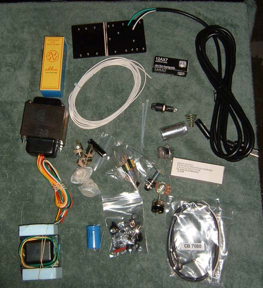
This past Tuesday, May 25, I ordered my combo amp kit from Allen Amps. David did the number one thing that a salesman should ALWAYS do. He under-promised and over-delivered. He told me that the amp would not get to me until June 1st at the earliest, and the cabinet a few weeks after that. To my surprise and happiness, they both arrived today. So what did I do? I opened up the boxes and I took pictures.
First things first. Do I know what I am doing. Not all. Will I let that stop me? No.
In fact, I opened the box with the amp parts and had my first "oh shit" moment. Oh well. I did not include a phot of the amp chassis because it is nice bright chrome and does not photograph well with anything short of pro gear which I don't have. But it sure is pretty.
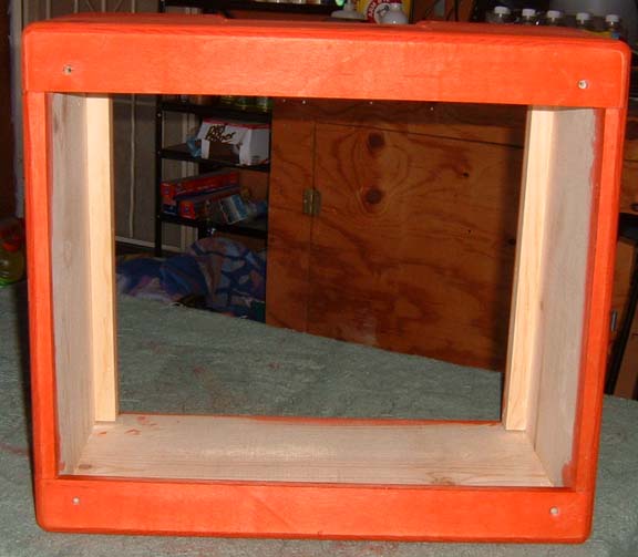
What I did, to save money and because I like wood working, is I ordered an unfinished cabinet. So I also ordered alchohol based dyes and some nitro. I was wondering how I was going to finish this cabinet. When I got it, I discovered I could remove the grill/speaker assembly, the handle, and feet very easily. They are held in with screws. So all I need to do is some partial dis-assembly, then I can sand and stain and nitro to my hearts delight.
Watch this page as I try to build a tube amp. It should be good for a few good laughs.
********************************
June 1, 2004
Today I took the cabinet out of the box and dis-assembled it for sanding. I removed the handle, the speaker and grill, and the feet. Then I used my trusty B&D power sander to sand it down to 400 grit. Power sanders are nice and fast.
If you should decide to do a natural wood finish, one thing to keep in mind is that these cabinets were designed and built to be covered by fabric, and the wood working quality matches that concept. Not a big deal, but it is something to keep in mind.
So I sanded down the rough spots and the pencil marks. No big deal.
I figured that the next step would to try and figure out how I would spray the nitro on this critter. It turns out that I can hang it like a neck and spray it that way. "Shou work"
The other thing that I did was to try to find a color that I wanted to dye this thing. I am using alchohol dyes, from LMII, for the first time. My first try was red & yellow, and that did not turn out. Then I tried red alone. YeeHah! I need to fine tune the strength of the dye, but I have my color.
One thing on the cabinet. They use pine wood for the cabinet, but it does have some nice grain in it. Tomorrow I stain/dye and maybe spray the first coat of nitro.
********************************
June 2, 2004
This is the red dye, standalone. No other colors, and before spraying.
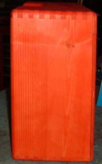
This is after a full can of StewMac Sanding Sealer Nitro.
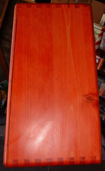
The color is off in this photo. It looks more orange than it should.
********************************
June 3, 2004
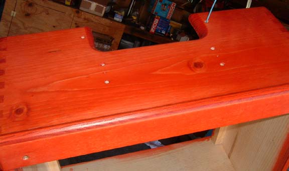
Yesterday a full can of sanding sealer. Today a full can of standard nitro. It looks pretty sharp. Now it has to dry for 2 weeks, or more. The next stage/step is the electronics.
********************************
June 8, 2004
Starting at instruction point 1 thru 2
One thing that you have to watch for on the mechanical drawing is perspective. You are looking from the front to the rear. I was a bit confused at first, but I finally got it.
I started the day like a good boy. I set up my work space, got the instructions out, found the parts mentioned in step #1 of the instructions and I immediately ground to a halt. I was not sure which was the power transformer and which the output transformer. So up to my luthier I went, and we got that one straightened out. The one with all the wires in the power transformer, and the one with fewer wires is the output transformer. Also, the transformers mount on the outside of the chassis, not the inside.
The first step is to make sure that the mounting holes for the output transformer are the proper size. Before that I had to figure out where it goes. We got that as well. This is not documented. Next is to do the holes for the PC board. There are no holes in the chassis that are aligned to the PC board to allow mounting of the PC board, but in step #2 is the implication that the holes are not marked/drilled in either the chassis or the board, that you have to locate them yourself. So I will send David Allen an email asking to confirm that belief.
********************************
June 9, 2004
Continuing point 1 thru point 8
David Allen got back to me last night, so all is good there. Here is the thing: A knowledge of the topography and layout of a Champ amplifier will go a long way towards answering many of the questions I have. Unfortunately, I have no such knowledge. This information is critical really in only two areas thus far, locating the output transformer and locating the PC boards. I think that I have located them correctly. And you have to drill your own holes in the PCBs and the chassis to mount the PCBs to the chassis.
Instruction point #2 implies that the PCBs and the output transformer mount to the same holes. Not so. Points 7 & 14 correct that impression.
On the mechanical drawing there is a 3rd hole below the speaker jack that I had to drill out.
Otherwise, points 1 thru 8 are pretty simple, just putting most of the big pieces in the chassis. The only thing missing is the PCBs and that is not even started yet. It comes next.
Point 4 has me installing the tube sockets, and I forgot about the perspective mentioned above, so I put them in backwards. Fortunately this is annoying, not earth shaking. A few screws and it is taken care of.
Point 9 is where you start stuffing capacitors and resistors into the PCB. Outside of the fact that my resistor reading skills are almost non-existant, this is actually pretty easy. In fairness, if you are familiar with the amp topography, up to this point should represent about 1 hours worth of work. Not much at all. To help with reading the resistors, I looked here. I think that I have them all in right, but I am not 100% sure. So I will be off to my luthier to double check.
********************************
June 11, 2004
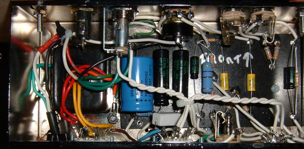
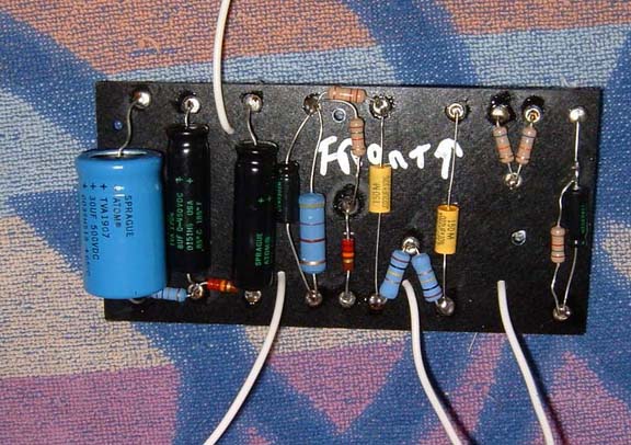
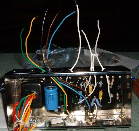
I have now completed thru point 12.5. I have installed/inserted all of the pieces on the PCB, soldered them, and trimmed the excess bits. The arrow that says "front" is actually pointing towards the front of the chassis, where the knobs are. The "back" is where the tubes will go. The transformers go on the top.
********************************
June 16, 2004
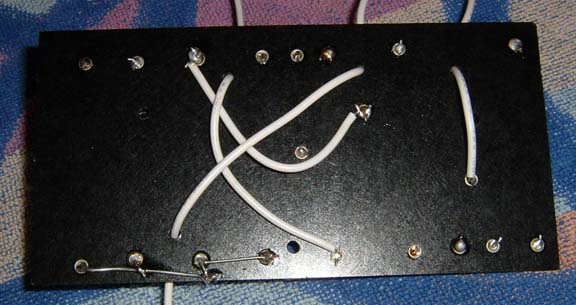
So I got this far:
And I had another "oh shit" moment. What you can not tell from the photo, unless you really know your amps, is that about half of the white wires are missing. So I had to dis-assemble the PC board and pull it out and put in more wires, in the correct location of course. I have had a very minor challenge with that as well. Double and triple check everything!!! Fortunately, pulling the board out before soldering is not hard at all. Two washers.
One challenge: This is a repeat of an earlier comment/complaint, but the mounting holes for the PCBs are not pre-drilled in either the PCBs or the chassis. So I had to drill some new holes for that. Oh well. No harm, no foul.
Another step or two tomorrow.......
********************************
June 29, 2004
So I got it all together, and I tested it. Nope. It don't work. I sent it back to David Allen, and apparently I did a pretty crappy job of it. I will take this as a message from the Almighty that building amps is NOT in my future.
********************************
July 15, 2004
I got the amp back from David a bit ago, while my wife was home on vacation and I could not mess with anything because she kept me busy. But... It works and sounds & looks good. I get some good growl type tone at moderate volume, which I really like.
Building amps in not something that I should ever do again.
********************************
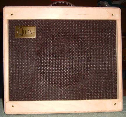
July 16, 2004
This is an after photo. Unfortunately, I did not take any before photo's. But trust me, this is much better looking, and it works.